


P.O. Box 470, Willits, CA 95490-0470, USA
Jerry: (707) 354-1048, 9
info@foothillmodelworks.com
Welcome to Foothill Model Works’ home on the net! This set of web pages is designed to provide our customers and friends with an online reference to our company and our products. Always a work in progress, please check back here from time to time. We now have our entire catalog of currently shipping products presented online. Drop me a line and tell me what you think or what other information you would like presented here.
See the “ ” link button on the left for information on ordering from FMW and how to contact us. We can now do invoicing through
 ![]() for our internet customers seeking a secure, online payment method. No more faxing or telephone tag necessary!
for our internet customers seeking a secure, online payment method. No more faxing or telephone tag necessary!
New Telephone Number!
We’ve finally given up on AT&T and land lines. AT&T’s service has become just too unreliable and, more importantly, too expensive. It took them over two weeks to restore service at our last outage (at Christmas time no less) and they left us with a ground hum they refuse to fix or even admit exists. Luckily, US Cellular has excellent coverage in our area and we were able to get new smart phones with unlimited text and talk for less then what we were paying for extremely basic cell phones and land lines!
Our new telephone number follows. We kept the same office hours and can still take messages. We usually can’t answer the phone while we’re working in shop, so be sure to leave a message if we don’t answer right away. Faxing is no longer available. Contacting us online remains unchanged.
Jerry: (707) 354-1048, 9
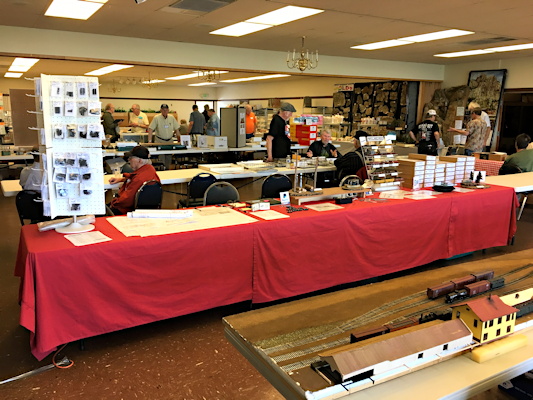
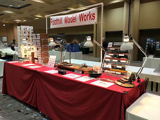
Thanks for Coming to See Us!
A big thank you goes out to the people who put on the Logging & Mining Modeler’s Convention in Sonora and O Scale West in Santa Clara this year and to all of our customers who made them a success. A great time was had by all. Hope to see you all again soon!
20′ Outside Framed Box/Fruit Car Kit Progress!
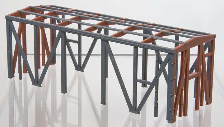
Test shots of side and end frame, and roof framing parts assembled.
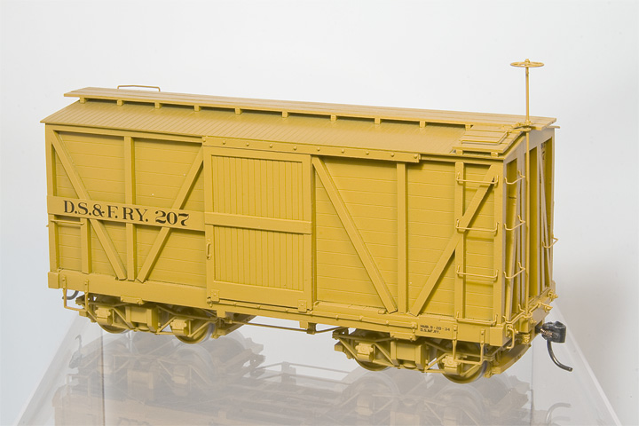
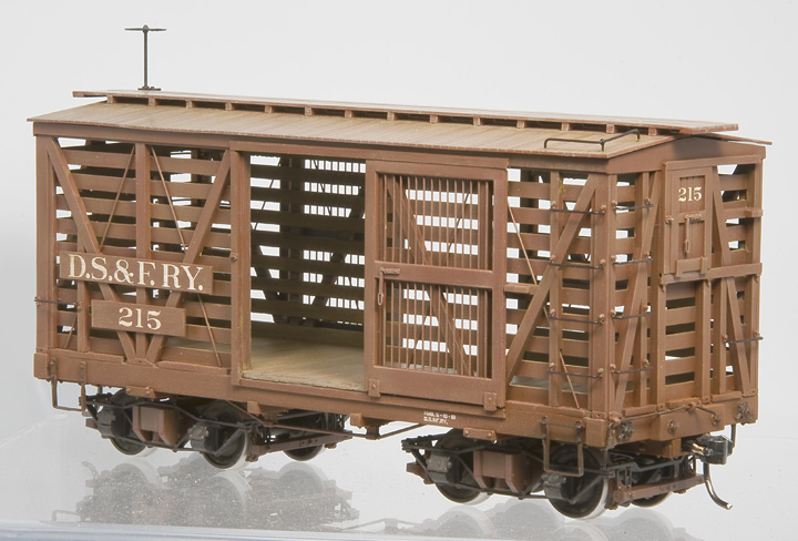
Pilot models of outside framed box car and fruit/stock car.
We’ve made progress on the 20′ outside framed, box and fruit car kits! Learn more and follow along with new developments on our our 7′ x 20′ Outside Frame Box/Fruit Car Progress Report page.
New Shipping & Handling Policy
Due to circumstances beyond our control, ever increasing shipping cost have forced us to abandon our flat rate, domestic shipping price policy. From now on (7/19/2013), all products shipped to addresses in the US, will be shipped at cost, via USPS Priority Mail. While this will benefit customers with small parts orders (USPS' smallest Priority Mail box typically ships for $5.25), larger kit order customers will see an increase and can go for around $12 to $16. International orders will remain as before, billed at cost. Shipping cost estimates will, of course, be provided for anyone who requests it at the time of their order.
Thank you for your understanding.
New Products!
 S.P. Standard No. 3, Wooden Turntable Drawing
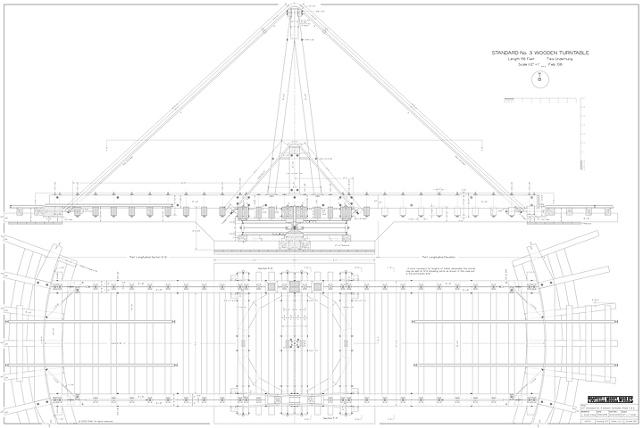
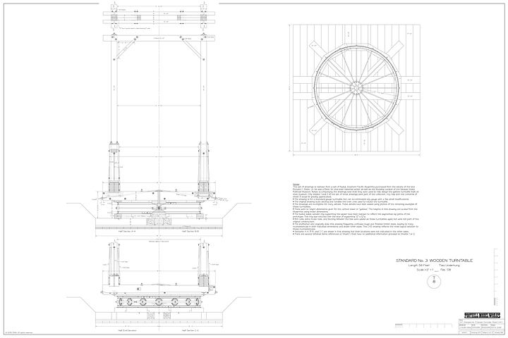
This set of drawings is redrawn from a set of faded, Southern Pacific, February 1908 blueprints purchased from the estate of the late Richard C. Datin, Jr. He was a Reno, NV and train historian writer as well as the founding curator of the Nevada State Railroad Museum. Notes accompanying the drawings said that they were used to help design the gallows turntable built at that museum. We are making these drawings available here to help keep this important information from fading away and to make it readily available for today’s and future modelers. Only sheets 1 and 2 of the set of three drawings were part of the collection. Any help with the contents of sheet 3 would be greatly appreciated!
A few notes on this set of drawings:
- The drawing is for a standard gauge turntable, but can accommodate any gauge with a few small modifications.
- The original drawing lacks decking and handles the train crew used to rotate the turntable.
- The drawings are incomplete for many details. These details have been added using photos of the remaining examples of these turntables.
- There were no height dimensions given for the central tower or “gallows.” The heights in this drawing are scaled from the blueprints using known dimensions.
- The twelve sided, wooden ring supporting the spider have been redrawn to reflect the segmented lap joints of the prototype. This ring was notched over the star of supporting 12″ x 12″s.
- Rim rails, extra truss rods, and blocking between the ties were added as these turntables aged; but were not part of the original construction.
- The draftsman who originally drew this drawing frequently confused rough and finished timber sizes, leading to many inconsistencies in both indicated dimensions and drawn timer sizes. This CAD drawing reflects the most logical solution to these inconsistencies.
- Sections A—A, B—B, and C—C are shown in this drawing, but their locations were not indicated in the other views.
- There are several lettered items referenced on Sheet 1, that have no additional information provided on Sheets 1 or 2.
S.P. Standard No. 3, Wooden Turntable Large-Format Drawing:
The set of drawings includes two, 36″ x 24″ sheets printed on plain paper.
| Scale | Stock No. | Price |
|---|---|---|
| 1/2″ | FMW-5003 | $15.00 |
Sketch of [S.P.] N.G. Tender Truck
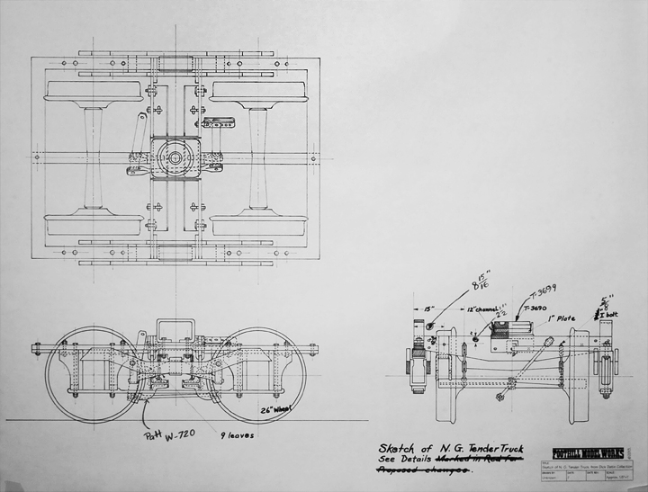
This is a direct copy of sketch of the structure of a narrow gauge tender truck purchased from the estate of the late Richard C. Datin, Jr. He was a Reno, NV and train historian writer as well as the founding curator of the Nevada State Railroad Museum. Date unknown. We are making these drawings available here to help keep this important information from fading away and to make it readily available for today’s and future modelers. While not an exact scale drawing, it does show a great deal of detail as to the structure and layout the tender trucks used on the Southern Pacific narrow gauge and its predecessor lines. Great info for anyone building their own set of trucks, or attempting to “correct” the currently available models!
Large-Format Sketch of [S.P.] N.G. Tender Truck:
This drawing consists of one, 23″ x 17.5″ sheet printed on plain paper.
| Scale | Stock No. | Price |
|---|---|---|
| Approx. 1 1/2″ | FMW-5004 | $5.00 |
O/On3/On30/On2 Griffin Wheel Co., 26″ Single Plate, Chilled Iron Wheels (in Celcon® )
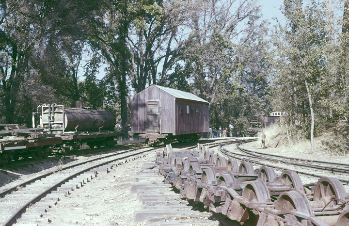
Wheel grinder track at West Side & Cherry Valley (Photo by Jerry Kitts, November 1978 at Tuolumne), filled with trucks using this Griffin 26″ single plate wheel. (No, we have no explanation for why the West Side thought it was OK to grind down the surface of chilled iron wheels.)
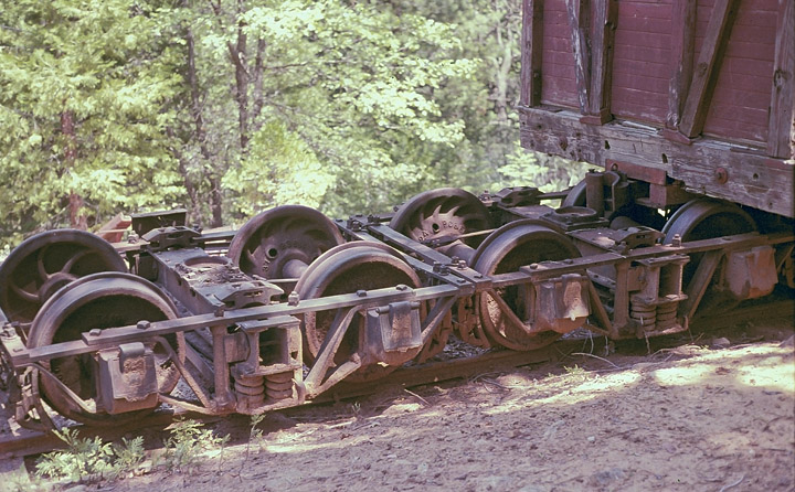
Pacific Car & Foundry, connected-truck, log car trucks from an ex-Swayne car. (Photo by Jerry Kitts, May 1978, at Yosemite Mountain Sugar Pine Railroad.) The first axle has this Griffin single plate wheel. The West Side had a habit of using any available wheel in any truck, as needed, so long as the diameter matched. We’ve even found a truck with four different wheels, including one A. Whitney & Sons wheel from the 19th century!
New, scale, Griffin Wheel Co., 26″ wheels! And we do mean scale (O Scale to be exact, gauge to be determined by axle length, just like the real thing). These are very accurate copies of their 1920’s, 26″ single plate, chilled iron wheels as ordered for and used on the West Side Lumber Co. These wheels are based on exacting measurements of those preserved in the Roaring Camp & Big Trees collection in Felton, California. We even cut the wheel tread to an exact match of period M.C.B./A.A.R. recommended practices (no mangling to match RP25 here). Also note as you look at the photos and read the captions, these wheels are only 0.5417″ in diameter (aka the detail really is that small)! Production has begun and the first batch has already shipped!
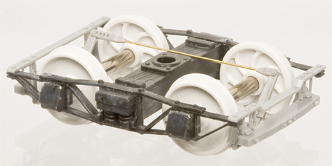
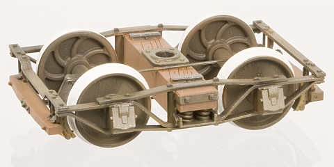
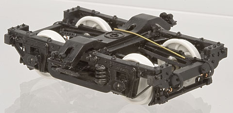
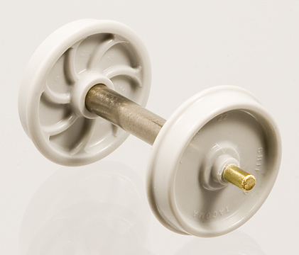
Griffin 26″ Wheels Sets (FMW-4011-On3) installed in MacLeod Western T-17-2 Truck w/FMW-4000 Wooden Brake Beams, FMW-4004 Truck Brake Levers, and FMW-4007 Celcon
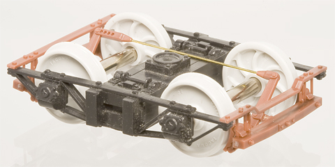
Griffin 26″ Wheels Sets (FMW-4011-On3) installed in MacLeod Western T-14 Truck w/FMW-4000 Wooden Brake Beams, FMW-4004 Truck Brake Levers, and FMW-4007 Celcon
Works in D&RGW trucks too! While the vast majority of the D&RGW’s wheels were Griffin 26″ Washburn pattern wheels, they existed for so long and had so many cars, that you can find examples of just about every kind of wheel. Including paper, single plate, and even turned steel wheels. Though they obviously got their wheels from the Denver plant, not the Tacoma plant.
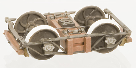
Griffin 26″ Wheels Sets (FMW-4011-On3) installed in a San Juan Car Co. D&RGW, 3′ 7″ Freight Car truck in brown. (Axle holes in San Juan trucks have to be drilled out as they are designed for a shorter, pointed axle.) |
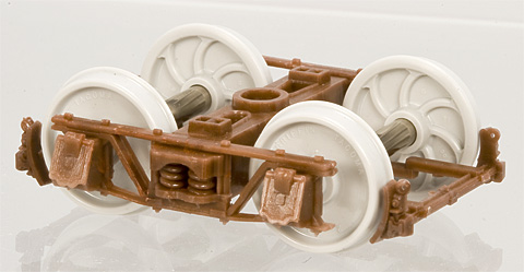
Griffin 26″ Wheels Sets (FMW-4011-On3) installed in a Grandt Line Products 3056 D&RGW Narrow Gauge Passenger Car Truck with Cast Steel Bearing Bolster w/3057 Brake Set. (With brake beams lowered to correct height for 26″ wheels.) |
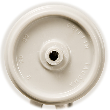
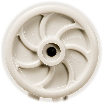
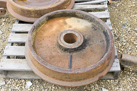
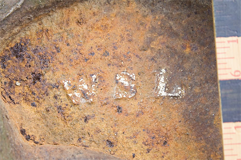
Front and Back of the new wheel. The wheels are shot from the center of the wheel, so there aren’t any nicks in the flange or along the rim. Nor did we use knock out pins. The letters were cut with a 0.003″ diameter end mill for scale 1/8″ thick letters! As the lettering cast into this wheel indicates, Griffin’s foundry in Tacoma, Washington cast this wheel specifically to order for the West Side Lumber Co. (WSL) on February 20, 1922 (the prototype for this specific wheel was serial # T263445). The “T1” refers to the taped measurement of the diameter of the wheel. I have no idea what the “G” and “3G” refer to.
A cross sectional view (cutting Celcon
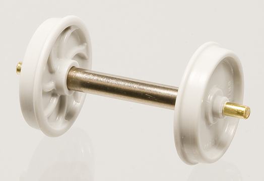
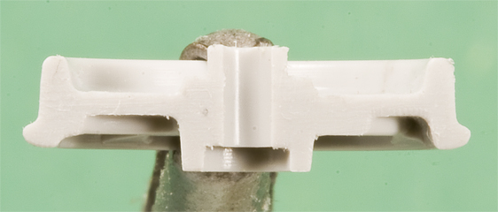
Assembled Wheel Sets (On3). We follow Cliff Grandt’s axle design for On3 - an exposed axle 1/16″ in diameter with an overall length of 1.165″. We’re using thin-walled, stainless steel, hypodermic tubing to simulate the straight, 5″ diameter axles of the prototype. They are not effected by under-track uncoupling magnets.
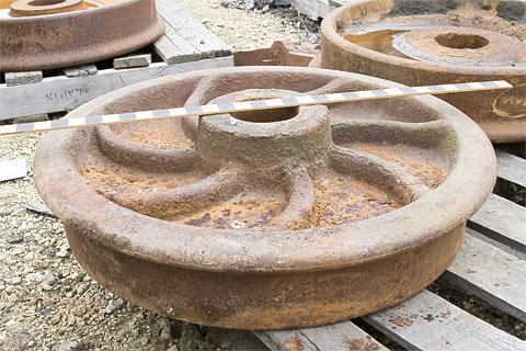
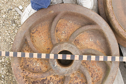
Griffin 26″, single plate wheel being measured and photographed at Roaring Camp & Big Trees, Felton, CA, on February 10, 2012 (10 days short of 90 years after the wheel was cast).
Produced in a bright, metal-like color, these wheels are cast in Celcon
Griffin Wheel Co., 26″ Single Plate, Chilled Iron Wheels (in Celcon® ):
These wheel sets include four axle sets in the following gauges. Recommended for use in Grandt Line Products, MacLeod Western, and most brass and white metal trucks. Not recommended for use in San Juan Car Co. trucks or any truck that uses pointed axles. All sales of custom axles are final and are non-returnable/non-refundable.
| Gauge | “Back-to-Back” Wheel Spacing | Axle Length | Description | Stock No. | Price |
|---|---|---|---|---|---|
| On2 | 0.416″ | 0.915″ | NMRA Standard On2 on NWSL Length Axles | FMW-4011-On2 | $10.00 |
| On30 | 0.566″ | 1.025″ | NMRA Standard On30 on HO Length Axles | FMW-4011-On30a | $10.00 |
| On30 | 0.566″ | 1.165″ | NMRA Standard On30 on On3 Length Axles (for use in On3 trucks) | FMW-4011-On30b | $10.00 |
| On3 | 0.666″ | 1.165″ | NMRA Standard On3 on Cliff Grandt/NWSL Length Axles | FMW-4011-On3 | $10.00 |
| Custom | Specified by Customer |
Specified by Customer |
Wheel sets built to customer’s specifications | FMW-4011-Custom | $10.00 |
Griffin Wheel Co., 26″ Single Plate, Chilled Iron (in Celcon® ) Scenery Wheels
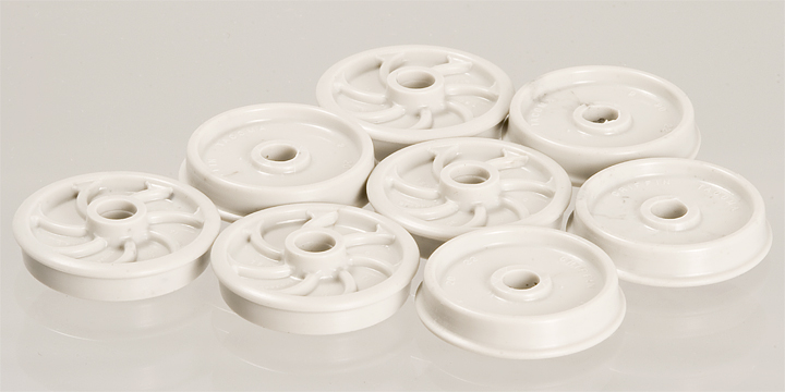
Does your junk or clutter pile need detailed, scale wheels? Does your wheel or car shop need a supply of new or used wheels? Does your snow plow or boom car need counter weights? Well, look no further! As we switch from styrene to Celcon
26″ Griffin Scenery Wheels:
Includes 8, Celcon
| Stock No. | Description | Price |
|---|---|---|
| FMW-4011-Scene | Set of 8, Celcon | $3.00 |
New Additions!
Zimo DCC!
We’re now proud to be Zimo DCC dealers! Check out the  link on the sidebar to learn more about this superb line of DCC sound decoders!
New MacLeod Western Parts!

Doug’s added some new parts to his line of styrene detail parts. Three new tank car tank ends, three new NBW castings, one new queen post, and three new trucks! Head on over to our MacLeod Western Parts List to learn more.
New Pages Added to: Getting it Right - The Bachmann On30 Climax
We’ve added three more pages to our comprehensive, illustrated guide to rebuild a Bachmann On30 Climax into a true, On3 Oil Burner to our Modeling Guide Pages!
- Page 1: Introduction, Taking it Apart. (rev. 9/28/2010)
- Page 2: Re-Gauging to On3, Replacing the Bell. (rev. 9/28/2010)
- Page 3: Re-building the Water Bunker & Oil Tank. (rev. 8/16/2011)
- Page 4: Adding a Rear Ladder & Water Tank Filling Hatch. (rev. 8/17/2011)
- Page 5: Oil Tank Details 101 & Oil Filling Hatch Body. (rev. 8/21/2011)
Featured Product of the “Week” (more or less)
American Car & Foundry, 24″ “Washburn” Pattern, Chilled Iron (in Celcon® ) Scenery Wheels
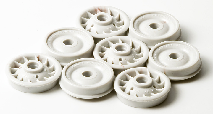
New for O Scale West 2012! Does your junk or clutter pile need detailed, scale wheels? Does your wheel or car shop need a supply of new or used wheels? Does your snow plow or boom car need counter weights? Well, look no further! As we switch from styrene to Celcon
24″ AC&F Scenery Wheels:
Includes 8, Celcon
| Stock No. | Description | Price |
|---|---|---|
| FMW-4006-Scene | Set of 8, Celcon | $3.00 |
General Information About Our Company:
-
Contacting Foothill Model Works
Our phone and FAX numbers, mailing and street addresses, and our e-mail address. -
Ordering from Foothill Model Works
Everything you need to know about placing an order with us.
We accept:


Online Product Listings:
-
FMW’s Detail Parts Catalog
Our illustrated detail parts catalog. -
FMW’s Rolling Stock Catalog
Our illustrated rolling stock kit catalog. -
FMW’s Structure Catalog
Our illustrated structure kit catalog. -
FMW’s Catalog Reprints
New series of period, prototype, catalog reprints. -
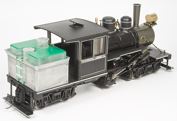
The Industrial Series in Classic Brass
Industrial locomotives and rolling stock, custom built in brass by FMW. -
MacLeod Western Detail Parts
Our current listing of prices and availability of these legendary detail parts. -
Zimo DCC Product Price List
FMW’s went DCC! Our online listing of this superb line of DCC motor and motor/sound decoders.
All text, images, and drawings ©2017, Foothill Model Works. Zimo logo is property of ZIMO ELEKTRONIK. Best viewed with standards compliant, cross-platform, CSS3 capable browser (Firefox, Safari, Chrome are good, FREE examples; Internet Explorer before v9 - not so much.).
Rev. 2/27/2018.