


Re-detailing The Bachmann On30 Climax
Re-building the Water Bunker & Oil Tank
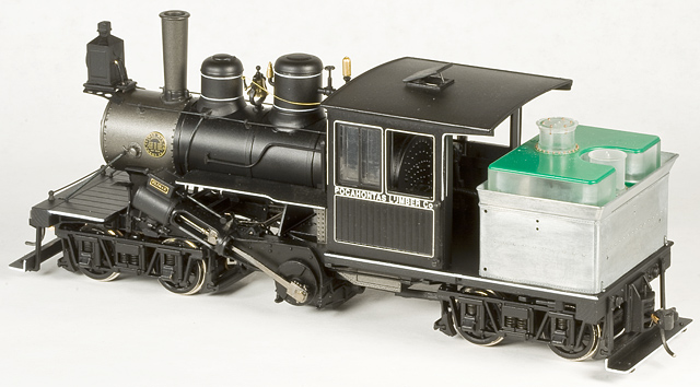
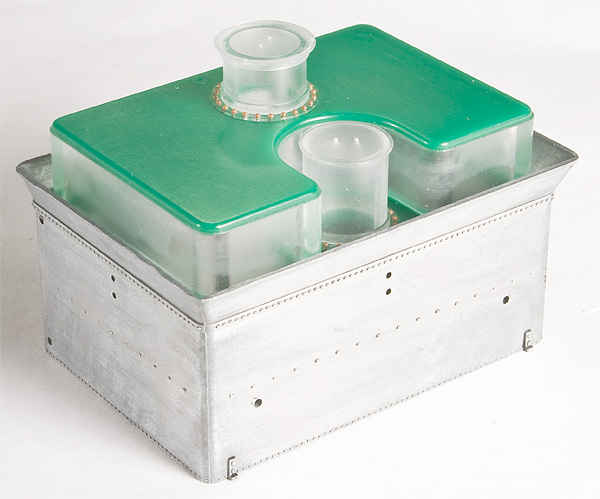
Bachmann Climax Conversion to Date (September 17, 2010).
Bachmann’s Parts vs. the Prototype:
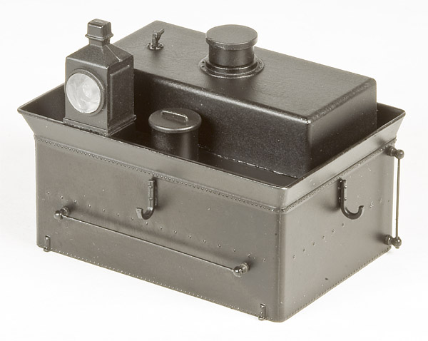
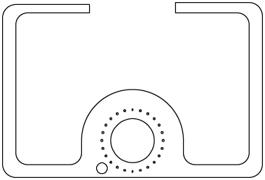
Stock Bachmann Water Bunker/Oil Tank (early version).
As I mentioned in the introduction, if you’re modeling a wood or coal burner, you’re in luck. The water bunker casting is correct for an earlier, wooden cab, Climax. All you really need to do is remove the syphon hose hooks (syphon hoses on Climaxes go forward under the running board and over the main rod and crank - they are NOT hung on hooks, over the head of the fireman, wrapped around the water bunker) and add a load fence extension around the top of the water bunker. I’ll cover the syphon hose correction later, but I’ll leave the load fence to wood/coal burner types. If you’re doing the steel cab version, the sloped sides to the water bunk top are OK, but not the norm. I’ll add a section on making straight sides when I talk about correcting the steel cab version. The water filling hatch is S scale as well (a.k.a., way too small for O scale), but I’ll be replacing it anyway as I redo the tank top. The front handgrabs are fine.
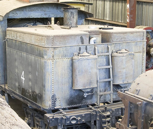
Pacific Lumber #38’s Water/Oil Bunker. The silver thing next to the water hatch lid isn’t part of the oil tank; neither is the rusty pipe next to the shovel.
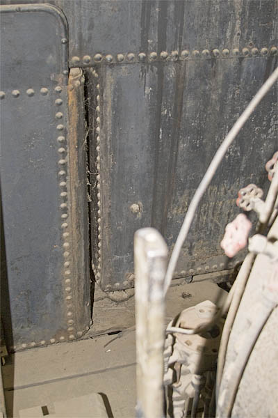
Oil tank front, showing extension between water legs. The large gap between the bottom of the oil tank and the deck is a mystery.
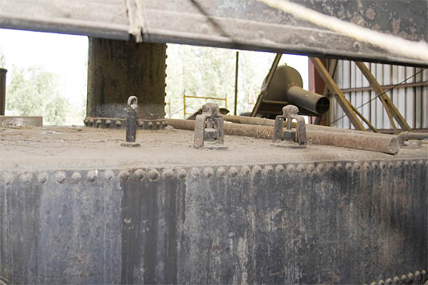
Oil tank fixtures (from left to right along front edge of tank): Dip Stick, Tank Drain (in open position - should be closed), Oil Supply Valve (in open position), random chunk of rusty pipe (not part of oil tank), Steam Heat Supply Pipe, and a shovel (no idea why it’s there, there’s nothing to shovel on an oil burner).
The oil burning version is a completely different matter. Climax simply didn’t make oil tanks in the way that Bachmann invented for this model. Oil tanks on Climaxes completely fill the top of the water bunk, right out to the edge (either factory built or as an add-on in a conversion), wrapping around the water filling hatch (or “manhole cover”), with either either squarish, inside corners or a large radius matching the water filling hatch. What’s missing? The dip stick, oil tank drain valve, steam heater supply pipe, syphon gooseneck (partially disassembled in the photo, it’s the 3″ I.D. elbow next to the water hatch), ladder, and the rear sanders (optional). What’s in the wrong place? The oil supply valve (it operates an opening on the bottom of the tank and, therefore doesn’t pass through the water leg - keep it though as it’s the right shape for an open valve and PSC’s part is a closed valve) and the rear headlight (we’ll get to that later). Unlike the more typical arrangement on Baldwin and Shay locomotives with the tank valve handle on top of the water legs, the water tank valve is a 90° globe valve on the bottom of the tank (We’ll correct that later too, as Bachmann only put one supply pipe on, on the fireman’s side only, and in the wrong place).
Getting Rid of the Unwanted Bits:
Probably the best part about this part of the whole project is that you don’t have to risk your own model to do it. Bachmann offers both the round headlight version and the square headlight version of the water tank as an inexpensive, $15 part assembly. They’re undec’ed (but painted black); so, if you want to preserve a tank assembly with a matching paint job, get and modify the replacement part. You can’t go wrong with a $15 insurance policy!
Starting with the water bunker removed from the engine (of course) and “fuel load” not in place (i.e. the oil tank, wood load, or coal load - they just press in place), remove the handrails and syphon hose hooks. Don’t worry about bending the handrails as the wire is easily replaced, just save the handrail posts. They can be ACCed in place, held on by the paint, or pressed into their mounting holes (or loose). Just be careful of the tank body if yours need “convincing.” Carefully remove the headlight. It’s ACCed in place. Gently rocking it back-and-forth should eventually pop the glue joint apart. The plastic insulator that the headlight leads passed through is also ACCed in place. It can be popped out from the inside using a screw driver. The plastic water hatch also needs to be removed and is ACCed in place.
Time to remove the paint. The water bunker casting is is die cast metal (i.e. no plastic to melt), so getting the paint off is fairly easy. Any paint thinner will do. We soaked ours in rubbing alcohol in a sealed container and scrubbed the softened/dissolved paint off with a stiff brush. (Rubbing alcohol is great for this. It’s non-toxic, so long as you don’t drink it, and safe to use on plastic parts too.) You should end up with a nicely detailed casting with some fine rivet detail and only a little bit of parting line filing to do. We’ll fill the unwanted holes after we install the new water tank “top.” By the way, if you end up with an uneven surface finish (which will show up when painted), try rubbing down the surface with super fine (#0000) steel wool.
The top of the water tank needs to be replaced and the headlight mount removed. The mounting tabs for the “fuel load” may as well come off too, with the resulting opening being as big as practicle; leaving lots of room for things like decoders and sound systems. This is best done on a small milling machine. Use the mounting screws that attach the bunker to the frame to mount the bunker to a flat piece of scrap stock. Then mount this set-up to the bed of your mill. If you set everything up square, it’s an easy matter to mill off the unwanted bits. Be sure to take light cuts. And be sure to check the squareness of your bunker before machining. The corner by the fireman’s side water leg was slightly warped on mine, leaving a tapered gap on my finished tank because I didn’t check first (the others we did this to were fine)! The headlight mount can be removed from the back slopped sheet either by rotating the head or by using and adjustable angle plate (We used an adjustable angle plate with great success).
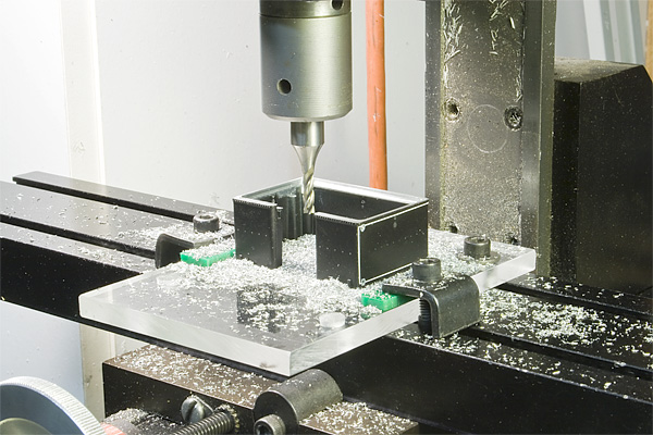
Forgot to take a photo of this step, but this does show the basic set-up. The bunker is mounted to a scrap piece of Plexiglas which is, in turn clamped to the bead of a Sherline Mill. (This bunker is having its sloped sides replaced with straight sides.)
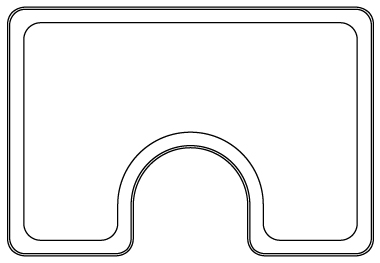
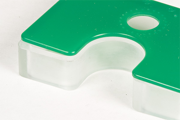
When you’re done, you should have a thin shelf running along the inside edge of tank, the same depth as the thickness of the material you are going to make your new top out off, wide enough to provide a good gluing surface.
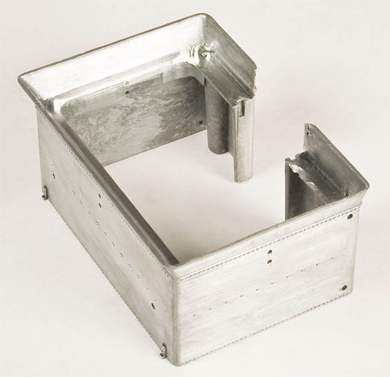
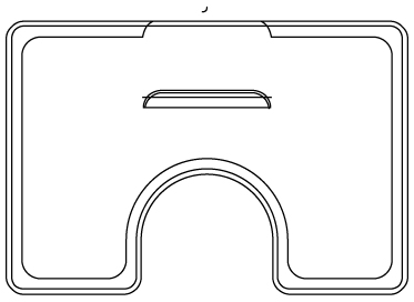
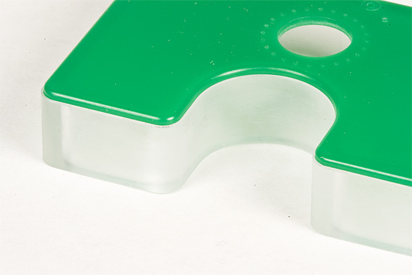
The finished part. Note the mounting shelf for the replacement water tank top. The back side of the front vertical sheet, by the water leg openings has also been machined flush with the rest of the sheet.
A Word About Materials & Making Parts:
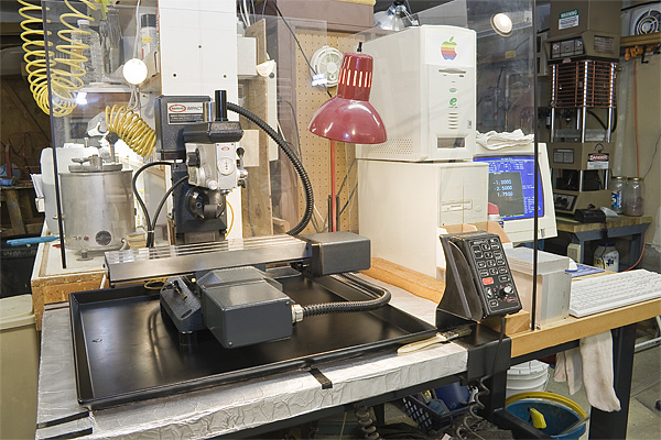
Our CNC Mill, a Servo Impact System II, in an unnaturally clean state.
What should be immediately obvious from here on out is that I have access to a high-end, bench top CNC milling machine (Expensive. Uses recirculating ball screws for zero backlash.). We use it here at Foothill Model Works to create parts for custom work (out of Plexiglas, aluminum, and brass) and to machine aluminum blocks to make dies for our plastic, injection molded parts. Does this mean that this project is impossible if you don’t have a CNC mill? Of course not. It will just take a bit more work. If you do have access to a CNC mill, like a converted Sherline, and want to machine plastic, I have a few words of advice.
First, don’t machine Evergreen styrene. While Evergreen styrene is probably the best quality styrene (strips, sheets, etc.) you can buy today, the titanium that it contains (the reason it’s white) eats cutters alive. A brand new cutter can go from sharp to completely worn out in a matter of mere minutes (I have the worn out cutters to prove it). Use ABS or Plexiglas (cast, never extruded) instead. As a bonus, ABS and Plexiglas is easily obtainable, comes in many different colors and sizes, and are cheap. The scrap bin at a place like Tap Plastics is a great place to look. Oh, and you may find colored Plexiglas a lot easier to work with than clear. As an added bonus, hard plastics like Plexiglas clean up beautifully to a nice metallic finish using fine steel wool (#000 or #0000 works great). Without dramatically rounding over exposed corners.
You don’t have to clamp down plastic. Clamp down a scrap piece of flat stock to the bed of your machine, then use double-sided adhesive tape to hold the part you want to cut. Double-sided tape has all the holding power you’ll need. Denatured alcohol will help “unstick” the part when it comes time to remove it from the scrap plate.
Feeds and speeds: light and fast. Generally, a lot faster than you can probably crank by hand. If you have a power feed or are using a CNC mill, experiment on scraps for the best results.
Lastly, and most importantly,
Basic Water Tank Top & Oil Tank:
Time to start adding back the parts we just removed. Since the oil tank will cover almost all of the top of water tank, you really only need to provide and edge around the outside of the oil tank and a shelf for the water hatch to sit on. If you’re not going to hollow out your oil tank for more vertical room, you can even use a simple rectangle (with rounded corners matching your end mill) with a small notch at the front for the vertical section of the oil tank, between the what would be the water legs.
Fancy, CNC version of water tank top. (JPEG not necessarily to scale.)
This is where having access to a CNC mill really pays off. While it is certainly possible to hand machine a solid oil tank out of plastic and then finish it off by hand, a CNC mill makes all of this work trivial (and more precisely detailed). Not to mention very easy to make more than one and have them all identical. The key to doing something as three dimensional (aka lots of under-cut detail in lots of different directions) as the oil tank is to carve the shape into easily machinable pieces. Since the prototype tank is really two tanks joined together (the main squarish tank on top of the water tank and another that fills the space between the water legs) you can use the natural seems of tank to carve the parts into pieces. My oil tank ended up being 5 pieces: a top sheet; a tall, hollowed out “ring” that represents the main body of the tank over the water tank; a thin strip that represents the bottom of this tank; a rectangular piece with rounded over sides that represents the front of the part of the tank between the water legs; and a short strip that represents the bottom of this tank. Because I carve up the tank this way, I was easily able to add things like the rounding over of the corners of the tops and bottoms (which were formed by drop forging) and adding a step to the top of the main tank body that results in a very precise 0.010″ lip that represents the sheet metal wrapped around the tank tops and bottoms. I also saved myself a lot of trouble by machining in the mounting flanges for the steam heat pipe, the two shut-off valves, and the dip stick.
CNC part outlines and tool paths for oil tank bottom, body, and top; respectively. (JPEGs not necessarily to scale.)
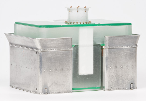
Oil tank top being fit into tank body edge detail.
The oil tank sub-assembly is quickly and easily assembled using acrylic cement (solvent based). I ended up adding a scrap piece of styrene as a backer to the tank front because I was worried about it being pinched off when handled. Be careful when gluing styrene to Plexiglas using acrylic cement. Plexiglas is a lot more resistant to chemical attack than styrene so it’s easy to over do it and melt styrene parts.
If you’re planning on adding rivet detail to the tank, nows the time to do it. Using decal rivets is probably the easiest way. Archer makes a good, clean looking sets, though I’ve never personally used them. In the end, I decided not to add rivet detail to all the seams on my oil tank. Since the Bachmann model didn’t have every rivet of the prototype, I thought adding all of those rivets would make the tank stand out too much and I was worried about matching the size of the rivets cast into the water tank. But this is purely a matter personal taste.
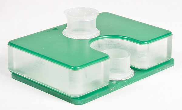
Oil tank sub-assembly with oil and water hatch stand-ins added.
Before adding the oil tank assembly to the water tank casting, you’ll need to fill all the unnecessary holes with putty. I used an automotive body putty and filled the notches for the water leg filler piece, the syphon hose hook holes, and the rear handrail post holes. I then ACCed the oil tank assembly in place on the water tank casting. Once you mount the water tank back in place on the engine, you’ll no doubt notice what I did: spending all that time making a correct, detailed oil tank front is a bit of a waste of time. It’s nearly impossible to see it around the cab!
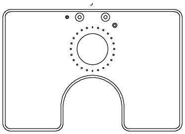
Oil tank installed in water tank casting. Some holes had yet to be filled and parting lines filed off in the rear view.
Continues on Next Page!
©2010, 2011, Scott Kitts. All rights reserved.
Rev. 3/28/2014.