


Re-detailing The Bachmann On30 Climax
Adding a Rear Ladder & Water Tank Filling Hatch
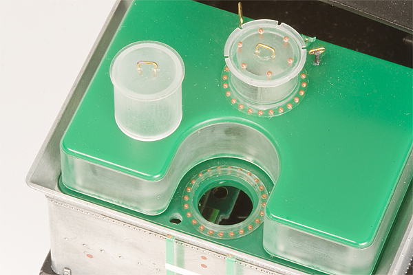
Bachmann Climax Conversion to Date (August 15, 2011).
Adding a Rear Ladder:
Rear ladder is missing from Bachmann engine.
The observant looking at this model have already probably noticed a small problem. There’s no way for the fireman to get on top of the water/oil bunker to fill the water tank or refuel (or maintain the rear headlight for that matter). Even with the ladder, you need to be part monkey to get up there (the ladder starts over chest high while you’re standing on the rear steps). Using Pacific Lumber No. 38 (it’s currently miss-labeled as Holmes-Eureka No. 4) and lots of prototype photos as a guide, it’s fairly easy to create a suitable ladder.
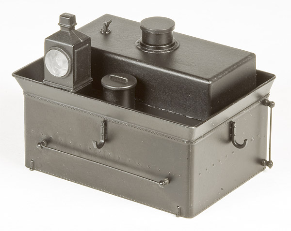
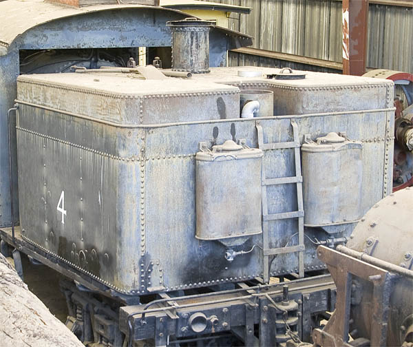
The ladder on the back of Pacific Lumber No. 38 is a simple one made from 2″ wide by 3/8″ thick strap stock, roughly 18″ wide, with about 16 1/8″ from top of rung to top of rung (12″ from the top of the top rung to the top of load fence). A single bolt mounts each end of the vertical straps. The tops are mounted through the rear load fence. The bottoms are mounted to the top of the end beam - or would have if the engine hadn’t been damaged in a log loading incident that bent the frame badly. The fuel bunker now sits at such a jaunty angle that a good 4″ or 5″ now separates the ladder from the end beam. The rungs are mounted to the vertical straps using two small rivets on either side. The bottom is spaced 6″ from the water tank. The ladder goes up straight for two rungs then tapers towards the top of the load fence.
Obviously, the ladder for the Bachmann climax will have to be different as the water bunker is smaller and the load fence is a different shape. The top of my ladder bolts to the top of the load fence just like Pacific Lumber No. 38, but the bottom will have to mount to the tank (above the rivet line), as the end beam doesn’t protrude but an 1″ past the back of the water tank. My ladder is straight and is 3″ from the back of the tank (the minimum required by the A.A.R./F.R.A.). I kept the 18″ width, but went with two rungs which gave a top-to-top spacing of 14 7/8″. Three was too crowded (with a 11 ¼″ spacing) and the bottom rung will be the rear handrail (to be added later).
If you’re only making one ladder, you can easily make it by bending 0.010″ × 0.040″ brass strap stock with a good set of pliers. Then gluing or soldering the rungs in place. I had to make several of these ladders and they needed to all look the same. So, back to the CNC mill. This is actually very easily done on a CNC mill. I just cut out the contour of the vertical straps from the side, from a 0.0417″ thick sheet of green Plexiglas using a 0.021″ diameter end mill.
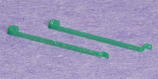
Ladder vertical straps as cut. The white stuff is left-over tape adhesive, which comes off with rubbing alcohol. The top strap is for a straight-sided water bunker.
There’s no way you hold something this small still while you glue it. The simple answer was to make a jig out of a piece of Plexiglas. The big holes around the joint areas are to keep the glue from wicking out of the joint and gluing the ladder to the jig.
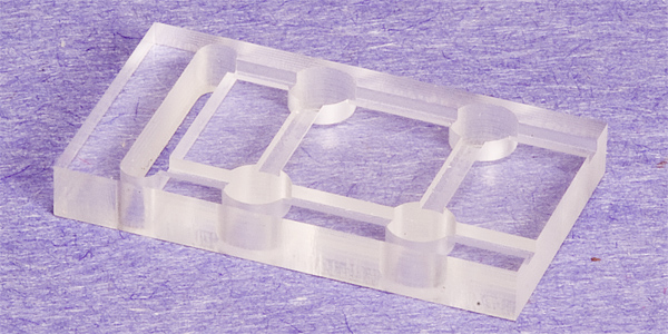
Plexiglas jig.
Pop the ladder sides in the jig. Cut a couple of Evergreen 0.010″ × 0.040″ styrene strips cut to 18″ long. Put them in the jig. And carefully glue them in place using solvent based, acrylic glue.
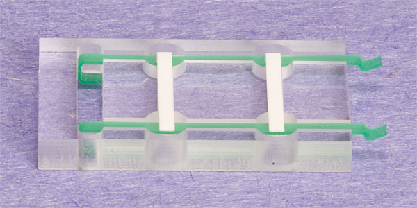
Completed ladder in jig (Macro lens perspective interferes with parallel lines, everything is actually square).
Once the glue dries, pop the completed ladder out. I found it easier to add the nut/bolt/washer castings after the ladder was ACCed in place on the water bunker rather than chase the ladder around on my workbench. I cut the shank off of the n/b/w castings and glued them to the surface of the ladder strap rather than drill holes. yes, I did use an Opti-Visor.
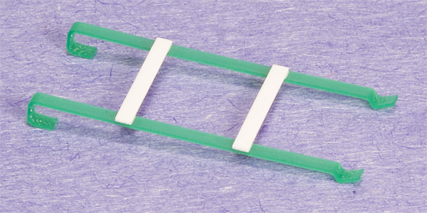
Completed ladder (Again the macro lens perspective interferes with parallel lines, everything is actually square).
The resulting ladder is actually quite strong and flexible (I was expecting it to be brittle). But, it will be nicely protected when the rear sanders are added. Everything came out nice and straight and square!
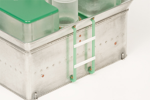
Completed ladder installed on water bunker.
Water Tank Filling Hatch:
The water hatch on Bachmann’s tank is a little small. A Grandt Line ¼″ scale water tank spout’s nozzle is about 9½″ in diameter and the Bachmann water hatch inside is about 13″ in diameter, leaving very little room for error when positioning your locomotive by the water tank to get water. Of course, if you’ve been following along, you’ve already obliterated it anyway. Luckily, it’s a fairly easy part to reproduce. It’s simply a tube (tall enough to clear the oil tank and big enough in diameter to accommodate your water tank spout, NOT “sized to match the relative size of the engine,” which is irrelevant) with a mounting flange on the bottom, and simple plug lid with a handle on top. If you’re going to add a proper syphon later, be sure to leave a hole in its side big enough to accommodate a 3 5/8″ O.D. (0.076″ Ø) pipe.
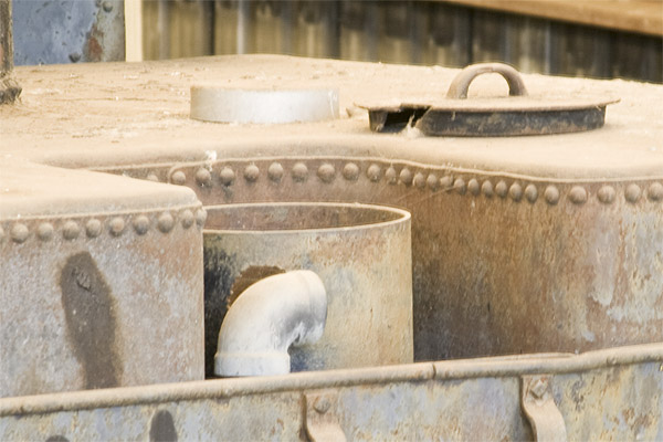
Pacific Lumber No. 38’s water hatch and lid (No, I have no idea how they managed to break such a large chunk out of the lid). Note the partially disassembled syphon pipe gooseneck elbow.
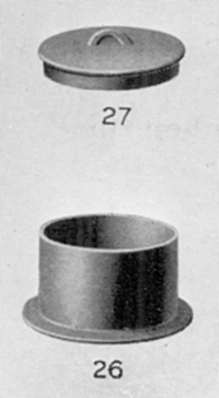
Tank man hole replacement parts (not really any specific locomotive), from Repair Parts, Shay Geared Locomotives, Catalog No. X 2, (Lima Locomotive Works Inc., 1921) 33, Plate 12 - Tank Valve, Syphon and Details. Parts 26 and 27, Tank man hole ring and Tank man hole cover.
While I’m sure somebody like PSC has a part that will work, this is probably one of the easiest parts to scratch build. All it takes a good, small lathe. I used my CNC mill and reused pieces of the oil hatch. My water hatch is 16 7/8″ in diameter and 18″ tall. I decided to get fancy with my lid and see if I could make it more like a shay lid which is in the shape of a very shallow, spherical dome. It worked, but it turned out to be unnecessary as you can barely see it on the model. The handle is brass wire. While I glued the mounting flange to the water tank top and the lid to the tube, I didn’t glue the tube to the water tank top yet. So, I could drill the hole for the syphon pipe later. I used Tichy rivets on the mounting flange. I also pre-drilled the rivet holes in the water tank top, so all I had to do would be to add rivets to line things up. Using fine steel wool on the parts cleaned them beautifully with very minimal effort (of course, it also polishes clear Plexiglas back to being transparent again - but, that’s what they make black paint for). Now all I have to do is find a decent 90°, 3 5/8″ O.D. pipe elbow that doesn’t look like crap for the syphon pipe gooseneck. Luckily, it can be added at any time before painting.
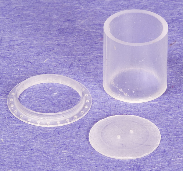
Raw water hatch parts after machining.
Water hatch partially assembled.
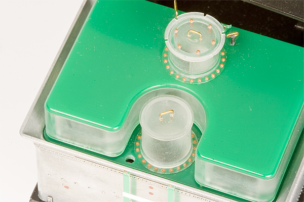
Water hatch mostly installed (not glued in yet).
Continues on Next Page!
©2011, Scott Kitts. All rights reserved.
Rev. 3/28/2014.