


O Scale Detail Parts
FMW-2201e Through FMW-4012
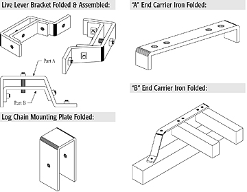
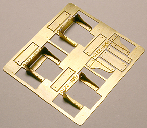
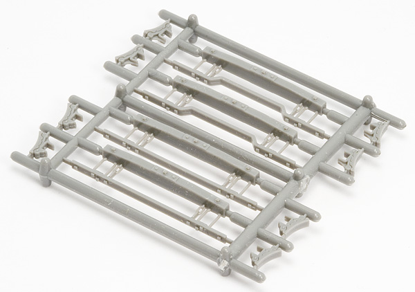
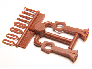
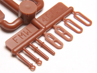
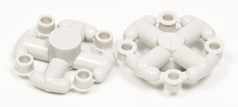
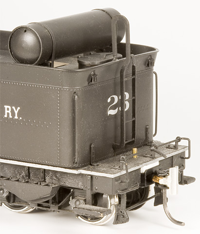
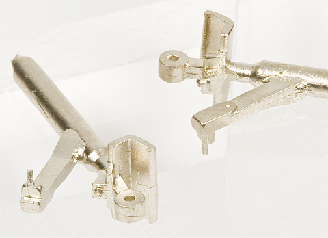
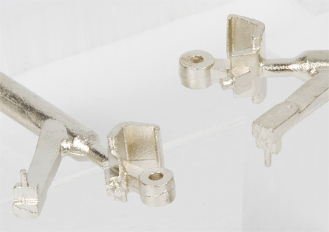
WSLCo. 24′ Hammond Flat Car Etchings & Chain Spool
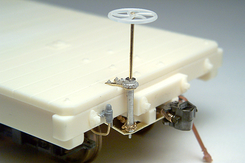
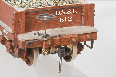
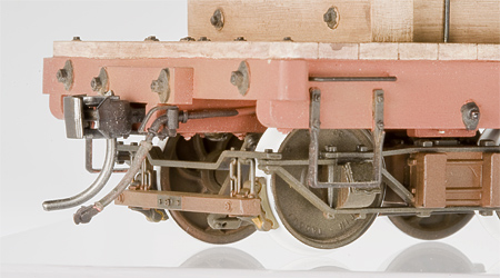
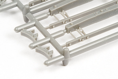
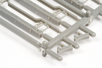
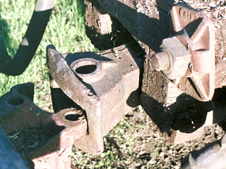
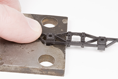
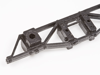
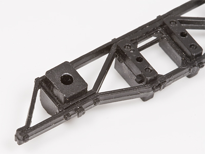
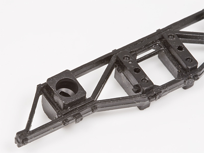
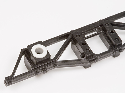
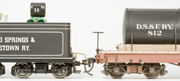
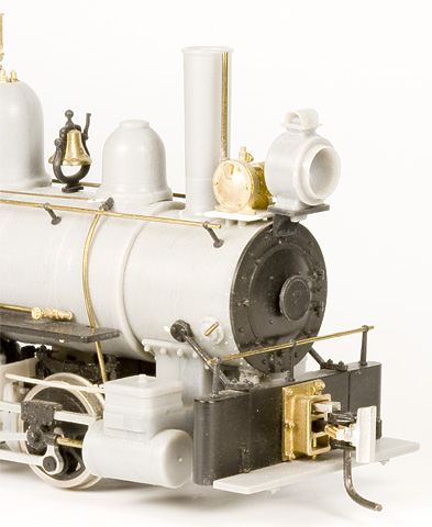
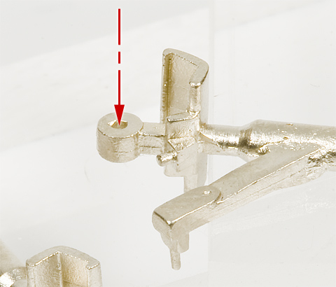
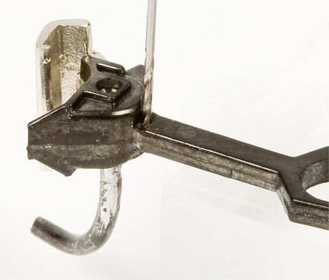
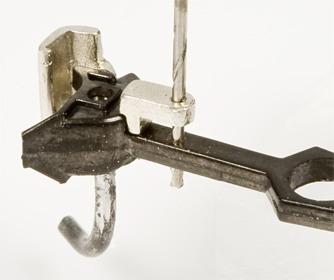
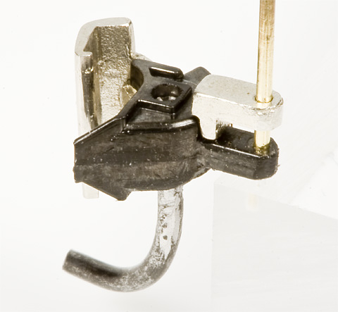
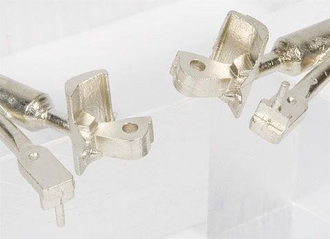
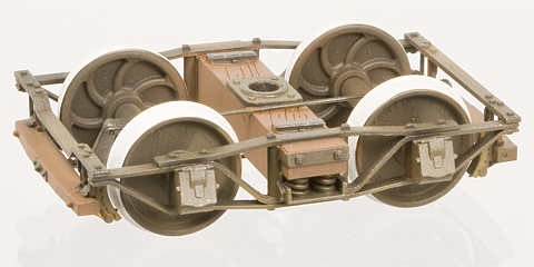
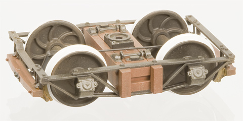
Lovested brake staff bracket, chain spool, and “B” end carrier iron from FMW-2201e installed on assembled FMW-2201 kit. |
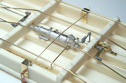
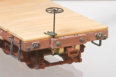
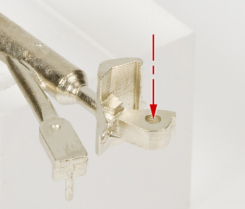
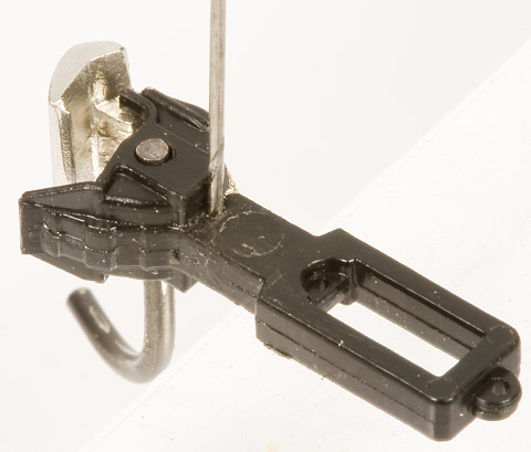
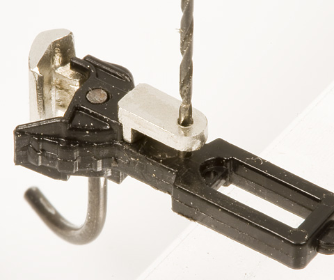
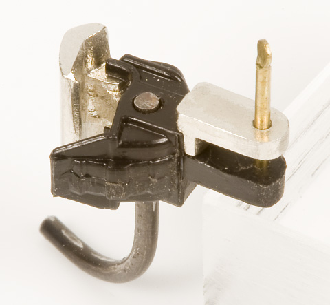
Various etchings from FMW-2201e installed on assembled FMW-2201 kit. |
|
|
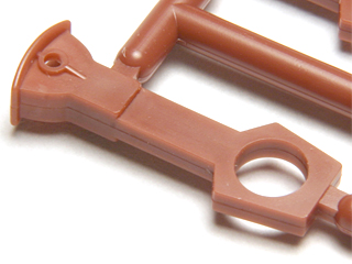
Originally part of our WSLCo. 24′ Hammond Flat Car Kit (FMW-2201), these parts are now offered separately for scratch-builders and for those looking to finish Carter Brothers/Hammond flat car kits produced by earlier manufacturers. Of note are the chain spool/ratchet & pawl casting and the upper brake staff bracket, which were produced using data and drawings from a vintage Lovsted catalog (supplier of many of the castings used by the WSLCo.). The log chain mounting plates fit 5″×12″ (0.1042″×0.1458″) side sills. The “A” end carrier iron fits 18″ (0.375″) wide (over outside) draft gear. Now available separately from our high quality, WSLCo. 24′ Hammond Flat Car kit, this set of brass etchings & chain spool casting feature the following:
|
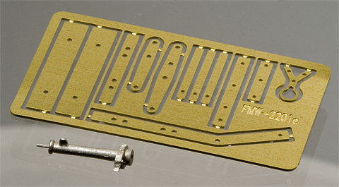
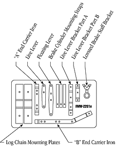
WSLCo. 24′ Hammond Flat Car Etchings & Chain Spool:
This kit includes all the brass etchings and castings shown above.
| Scale | Stock No. | Price |
|---|---|---|
| O | FMW-2201e | $12.00 |
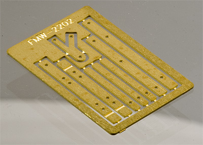
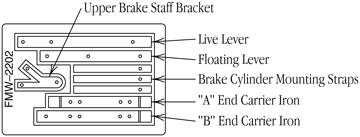
WSLCo. Standard 24′ Flat Car Etchings
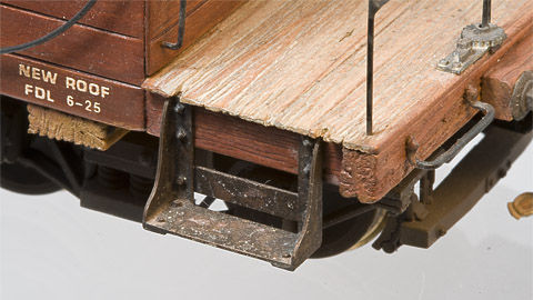
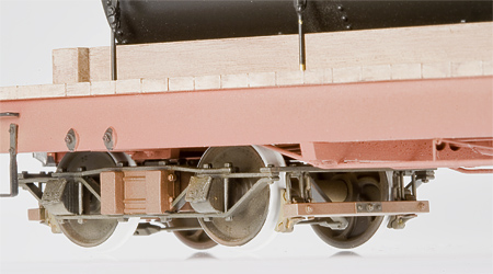
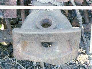
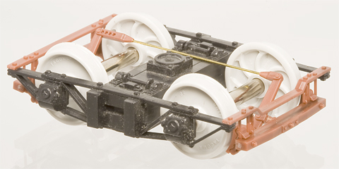
Upper brake staff bracket and “B” end carrier iron from FMW-2202e installed on assembled Design-Tech DT-114, 18′ High Side Gondola kit. |
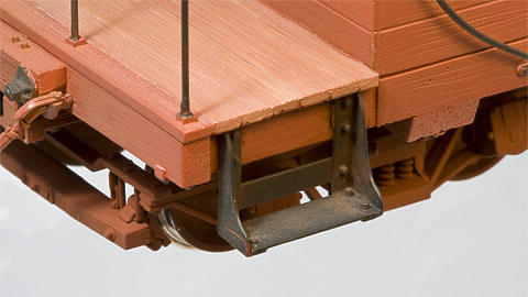
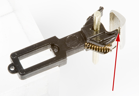
Upper brake staff bracket and “B” end carrier iron from FMW-2202e installed on assembled, urethane, FMW-2222 20′ Sand & Gravel Car kit. Car is also equipped with FMW-4005 Link & Pin couplers. |
|
|
Originally part of our WSLCo. Standard 24′ Flat Car Kit (FMW-2202), these parts are now offered separately for scratch-builders and for those looking to finish WSLCo. flat car kits produced by earlier manufacturers. The “A” end carrier iron fits 20″ (0.4167″) wide (over outside) draft gear. Now available separately from our high quality, WSLCo. 24′ Flat Car kits, this set of brass etchings feature the following:
|
WSLCo. Standard 24′ Flat Car Etchings:
This kit includes all the brass etchings shown above.
| Scale | Stock No. | Price |
|---|---|---|
| O | FMW-2202e | $3.00 |
WSLCo. Etched Brass Short Caboose Steps
FMW-2210a Caboose Steps assembled and installed on completed, Simpson, West Side Lumber, First Caboose 3, as built, c1942 kit. |
FMW-2210a Caboose Steps assembled and installed on completed, FMW-2210 WSLCo. Short Caboose #3 kit. |
|
|
Originally offered as a part of our WSLCo. Short Caboose kit FMW-2210, they are also offered here separately. Whether we’re replacing the “paper cut-out” steps of a previously manufactured kit or just adding them to the vulnerable corners of a new model, the half-hard brass construction adds the necessary strength. And the illustrated instructions and built-in assembly jig make assembly a snap. These beautiful, precise steps make a great addition to any model caboose project. Now available separately from our high quality, WSLCo. short caboose kit, this set of four, etched brass caboose steps feature the following:
|

WSLCo. Etched Brass Short Caboose Steps:
This kit includes all the etchings and castings required to complete four short caboose steps.
| Scale | Stock No. | Price |
|---|---|---|
| O | FMW-2210a | $TBA (Out of Stock) |
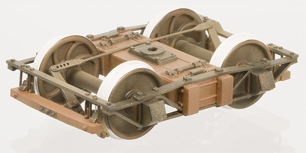
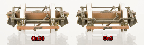
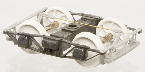
On3 Wooden Brake Beams, in Injection Molded Styrene
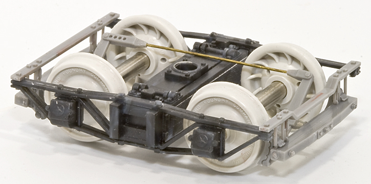
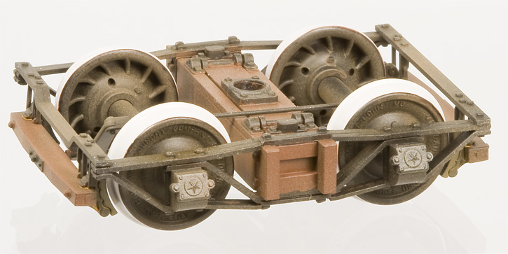
Completed, painted T-3 Truck; with FMW-4011-On3 26″ wheel sets, FMW-4000 Brake Beams, FMW-4004 Truck Brake Levers (modified with brass wire), and FMW-4007 Celcon® Bearing Inserts. (FMW detail parts are sold separately and are not included with MacLeod Western trucks.)
Adds that finishing touch that makes all the difference!
Installed on T-3 trucks and used on a completed FMW-2201 kit.
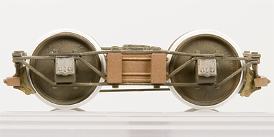 Installed on MacLeod Western T-3 truck. |
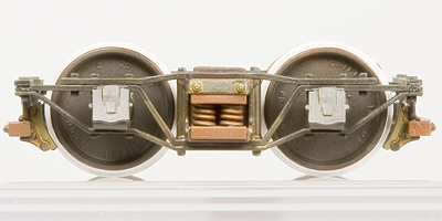 Installed on MacLeod Western T-12 truck. |
 Installed on MacLeod Western T-14 truck. |
 Installed on MacLeod Western T-16 truck. |
 Installed on MacLeod Western T-17-2 truck. |
 Installed on MacLeod Western T-18-2 truck. |
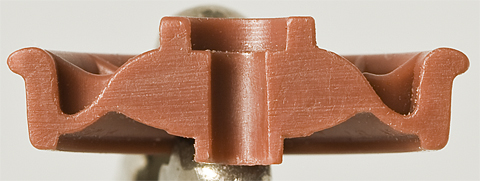
The first part in Foothill Model Works’ transition to styrene injection molded kits is this set of wooden brake beams. Based on measurements of a WSLCo. Camp Niagra camp car’s wooden brake beam, this incredible accurate, highly detailed part fills in one of the last remaining missing detail parts of a West Coast arch bar truck - the brake beams. The detail has to be seen to be believed, in fact, you might even need a magnifying glass (Check out the Cotter Pin holding the brake shoe mounting rod in place)! Rest assured though, their styrene construction means they’re durable enough for day to day operations on your layout. One look and we’re sure you’ll agree, you won't be satisfied without them anymore!
Want to use them in
This set of high quality, On3, Styrene castings features the following:
- Made of easy to assemble and paint styrene.
- Incredible detail and accuracy.
- Suitable for several railroads, including the WSLCo., SPC, NPC and many other western railroads.
- Fits a number of different MacLeod Western and Simpson trucks.
- Easy to follow, photographic instructions by FMW.
On3 Wooden Brake Beams:
This set of castings includes all the styrene castings required to complete one set of brake beams for one pair of trucks (trucks, wheels, car kit, brake levers, glue, and paint not included).
| Scale |
Stock No. |
Price |
|---|---|---|
| On3 | FMW-4000 | $6.00 |
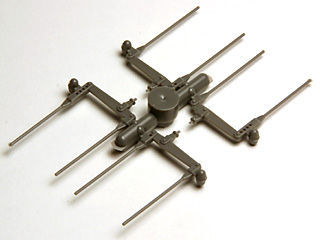
ACME 15″ Brake Wheel
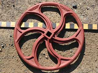
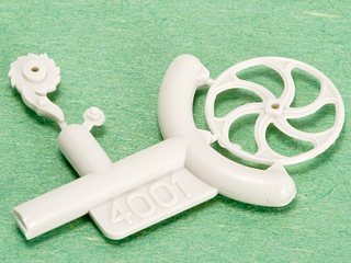
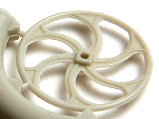
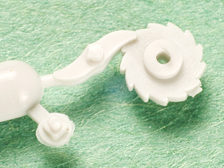
Our first 2005 addition to our growing line of O scale, plastic detail parts (cast in Celcon
ACME 15″ Brake Wheel w/Ratchet & Pawl:
This parts set includes one brake wheel and one ratchet & pawl casting.
| Scale |
Stock No. |
Price |
|---|---|---|
| O | FMW-4001 | $1.50 |
Code 70 Fishplates
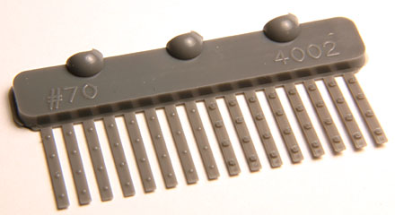
Commonly used on this rail size into the early 20
Code 70 Fishplates:
This parts set includes 5 code 70 fishplate sprues, enough to simulate 40 rail joints.
| Scale |
Stock No. |
Price |
|---|---|---|
| O | FMW-4002 | $3.50 |
Code 83 Fishplates
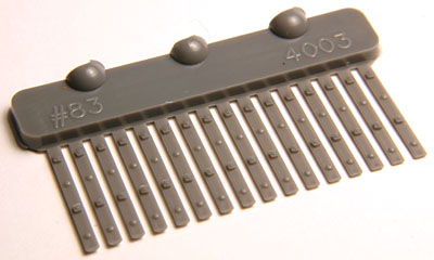
Commonly used on this rail size into the early 20
Code 83 Fishplates:
This parts set includes 5 code 83 fishplate sprues, enough to simulate 40 rail joints.
| Scale |
Stock No. |
Price |
|---|---|---|
| O | FMW-4003 | $3.50 |
Truck Brake Levers
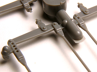
This part set represents the rods and levers that pull the brake beams towards the wheels when the brakes are applied. The companions to our On3 Wooden Brake Beams in styrene (FMW-4000), they add that finishing touch to a super-detailed model; especially on cars where the brake system is highly visible (like our NCNGRR box car kit or a skeleton log car).
Truck Brake Levers:
This parts set includes 4 brake levers, enough to complete one pair of trucks.
| Scale |
Stock No. |
Price |
|---|---|---|
| O | FMW-4004 | $3.00 |
Link & Pin Couplers
Inspired by the those used by the West Side Lumber Company, these link and pin couplers are designed to fit on a car designed to use Kadee
Link & Pin Couplers:
This single set includes 2 link & pin couplers (drawheads), 4 links, and 4 pins. The bulk pack includes 10 sets of these castings.
| Scale |
Stock No. |
Description |
Price |
|---|---|---|---|
| O | FMW-4005 | Single pair of link & pin couplers. | $3.00 |
| O | FMW-4005/10 | 10 pairs of link & pin couplers. | $25.00 |
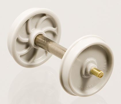
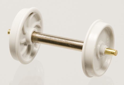
O/On3/On30/On2 American Car & Foundry, 24″ “Washburn” Pattern, Chilled Iron Wheels (in Celcon® )
Something new, scale American Car & Foundry, 24″ wheels! And we do mean scale (O Scale to be exact, gauge to be determined by axle length, just like the real thing). These are very accurate copies of 24″ double plate or “Washburn” pattern, chilled iron wheels used on the Casper, South Fork, & Eastern and Mendocino Lumber Co. disconnects based on exacting measurements of those preserved in the Roots of Motive Power collection in Willits, California. We even cut the wheel tread to an exact match of period M.C.B./A.A.R. recommended practices (no mangling to match RP25 here). Also note as you look at the photos and read the captions, these wheels are only 0.5″ in diameter (aka the detail really is that small)! Production has begun and the first batch has already shipped!
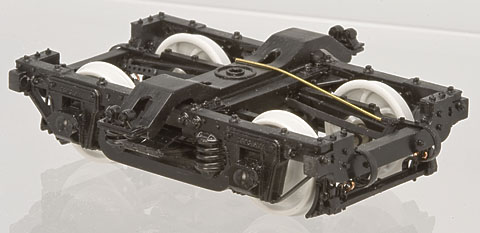
New Wheels Sets installed in MacLeod Western T-16 Truck w/FMW-4000 Wooden Brake Beams, FMW-4007 Celcon® Bearing Inserts, and FMW-4004 Truck Brake Levers. (Yes, I did replace the cast brake rods with 0.0156″ wire. And, yes, I know the tops of the two levers aren’t suppose to be connected. I do it that way to keep the rods from interfering with the operation of the trucks - it doesn’t show on the finished model.)
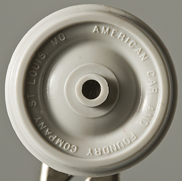
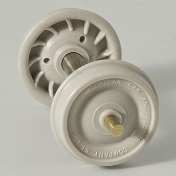
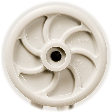
Front and Back of the new wheel. The wheels are shot from the center of the wheel, so there aren’t any nicks in the flange or along the rim. Nor did we use knock out pins. The letters were cut with a 0.003″ diameter end mill for scale 1/8″ thick letters! The small rectangle on the back of the wheel is the gate or the place where the sand casting was filled on the prototype (which never seemed to be in the same place twice), the three holes were used to support while casting and drain the sand afterward that formed the hollow (or double plate) of the prototype, see below. Note: the 1/8″ thick arc on the back of the wheels is correct. AC&F didn’t build these disconnects specifically for the C.S.F.&E. or the M.L.Co., they were built as catalog items, hence the dash. Had they been built specifically for the C.S.F.&E. or the M.L.Co., the railroads initials would have appeared here (true for any built to order wheel/car order, no matter how small the railroad - even the NCNGRR’s wheels had their initials on them).
A cross sectional view of an early styrene test shot (cutting Celcon
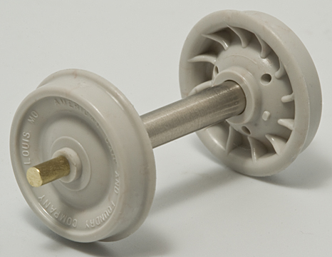
Assembled Wheel Sets (On3). We follow Cliff Grandt’s axle design for On3 - an exposed axle 1/16″ in diameter with an overall length of 1.165″. We’re using thin-walled, stainless steel, hypodermic tubing to simulate the straight, 5″ diameter axles of the prototype. They are not effected by under-track uncoupling magnets.
Typical AC&F 24″ wheels being measured and photographed at Roots of Motive Power, Willits, CA. Note the build-up of “stuff” of the face of the wheels on the left. Sometimes a lot of die cutting work will get lost in the real world.
Produced in a bright, metal-like color, these wheels are cast in Celcon
American Car & Foundry, 24″ “Washburn” Pattern, Chilled Iron Wheels (in Celcon® ):
These wheel sets include four axle sets in the following gauges. Recommended for use in Grandt Line Products, MacLeod Western, and most brass and white metal trucks. Not recommended for use in San Juan Car Co. trucks or any truck that uses pointed axles. All sales of custom axles are final and are non-returnable/non-refundable.
| Gauge | “Back-to-Back” Wheel Spacing | Axle Length | Description | Stock No. | Price |
|---|---|---|---|---|---|
| On2 | 0.416″ | 0.915″ | NMRA Standard On2 on NWSL Length Axles | FMW-4006-On2 | $10.00 |
| On30 | 0.566″ | 1.025″ | NMRA Standard On30 on HO Length Axles | FMW-4006-On30a | $10.00 |
| On30 | 0.566″ | 1.165″ | NMRA Standard On30 on On3 Length Axles (for use in On3 trucks) | FMW-4006-On30b | $10.00 |
| On30 | 0.566″ | 1.250″ | NMRA Standard On30 on Special, Long Axles (for use in MacLeod Western, T-2, On3 trucks) | FMW-4006-On30c | $10.00 |
| On3 | 0.666″ | 1.165″ | NMRA Standard On3 on Cliff Grandt/NWSL Length Axles | FMW-4006-On3 | $10.00 |
| Custom | Specified by Customer |
Specified by Customer |
Wheel sets built to customer’s specifications | FMW-4006-Custom | $10.00 |
 American Car & Foundry, 24″ “Washburn” Pattern, Chilled Iron (in Celcon
® ) Scenery Wheels
Does your junk or clutter pile need detailed, scale wheels? Does your wheel or car shop need a supply of new or used wheels? Does your snow plow or boom car need counter weights? Well, look no further! As we switch from styrene to Celcon
24″ AC&F Scenery Wheels:
Includes 8, Celcon
| Scale | Stock No. | Description | Price |
|---|---|---|---|
| O | FMW-4006-Scene | Set of 8, Celcon | $3.00 |
MacLeod Western Truck Bearing Inserts
Introduction:
We have long been huge fans of MacLeod Western’s line of trucks and detail parts. Without them, we would be stuck in a world of really expensive, brass trucks and/or an unending supply of “yet another pair of Delrin
The quick and dirty fix: lubricating the journals. A good, plastic compatible oil can help, but the oil can effect the paint. Packing the journals with graphite works well too. Unfortunately, neither solution is permanent and will have to be redone from time to time.
The more permanent solution: a bearing insert. Those of you who remember Russ Simpon’s West Side Lumber Co. trucks (which were also styrene) will remember that he used half of a brass rivet as a bearing insert. This worked well, but still needed oil for the brass-on-brass wearing surface and finding a reliable supply in the days of Chinese manufacturing is, well, “problematic.” So, we decided to make our own bearing inserts cast out of the same long wearing, Celcon
The result: Beautifully free-rolling truck without squeaks or the need for oil!
A friendly word of warning: While modifying MacLeod Western’s trucks for these bearing inserts is not especially difficult, it does require some specialized tools and does have the risk of breaking the sideframes. Proceed at your own risk as
Tools Required:
-
A 7/64″ (0.1094″) Drill Bit. A good one (aka NOT from Wal�Mart or Harbor Freight). Unfortunately, most drill bits are made for drilling into steel or wood, and are, therefore, WAY too aggressive. The helical angles and rake angles are too high for plastic. In short, they
will snag in the first 1/4 turn and rip the sideframe apart. If you have a good 7/64″ drill bit that cuts a straight, true hole, you can grind the rake angle on the tip to a flat, 0°. So the tip will scrape, rather than cut like a chisel. I started off with a D-bit cutter I ground myself with the same rake angle. If your name isn't Scott Kitts, the simplest solution is to just buy a good straight-flute drill bit. McMaster-Carr has one for $11.19 (part No. 8944A14).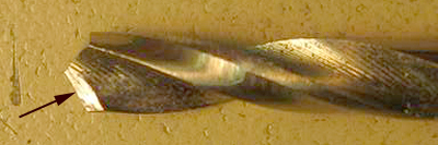
Standard twist drill with hand-ground, zero-degree rake angle (along edge indicated by arrow) for scraping. Courtesy a machinist friend.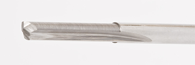
Commercial, straight-flute drill bit.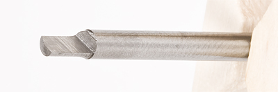
Hand made, D-Bit drill bit. -
A Drill Press. One with a good chuck and that you can control the speed of. One of those contraptions that converts a Dremel Tool into a drill press would
NOT be a good idea here (its 5,000 to 35,000rpmsWILL turn your sideframe into a puddle of goo). You’re looking for around 200-300rpm. We use a Cameron Micro Drill Press Series 164 with a speed control (Variable Speed Control Model 2A), an Albrecht chuck (0-1/8″), and a dial indicator depth gauge (we used one from Harbor Freight). A small milling machine like a Sherline or a Unimat would also work. I can’t see a pin vise working well here. -
A Jig or Clamp. A jig can be something as simple as a plate with a hole in it. Basically, you’re looking to hold the sideframe flat, securely.
Random junk plate with holes in it as a jig. With “ultra-safe” finger clamp.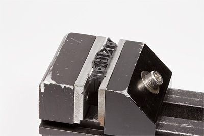
Sideframe held in Sherline vise. Sideframe may need to be shimmed to get secure hold.
Drilling Notes:
|
|
|
|
|
|
|
|
|
MacLeod Western Truck Bearing Inserts:
Detail part set includes a set 8, Celcon
| Stock No. | Description | Price |
|---|---|---|
| FMW-4007 | Set of 8, Celcon | $3.00 |
| FMW-4007a | Installation of 8 bearing inserts into new MacLeod Western truck kit, supplied by customer. Price includes bearings, but does not include price of trucks or return shipping costs. | $8.00 |
| FMW-4007b | Installation of 8 bearing inserts into new MacLeod Western truck kit, supplied by FMW. Price includes bearings and price of trucks, but does not include shipping. | $16.50 |
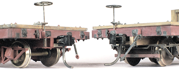
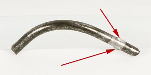
Extended Knuckles for Kadee® #5 Head, McHenry™ HO Couplers, or Bachmann® E-Z Mate® Mark II HO Couplers
and Kadee® #803 On3 Couplers
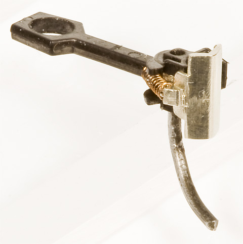
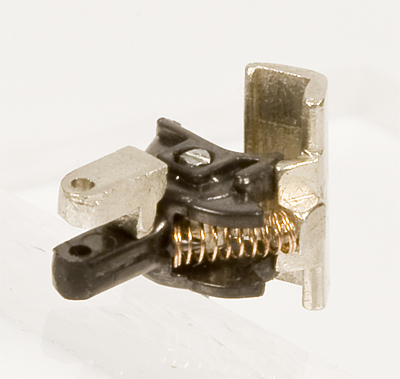
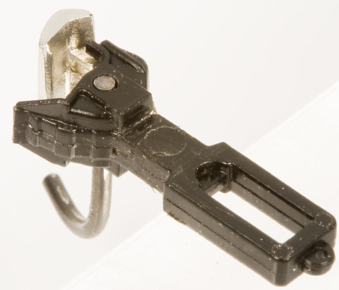
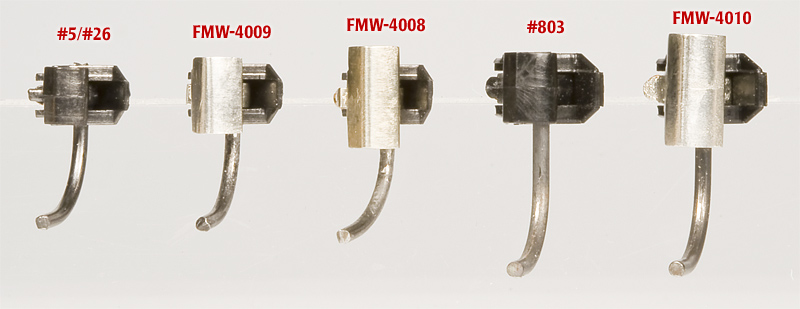
From Left to Right: Standard Kadee
Introduction:
Extended knuckle coupler installed in link & pin draw head on the Robert Dollar shay, Roots of Motive Power, Willits, CA, 5/20/2005. Yes, the draw head IS mounted upside down; No, I don’t know why. It was that way in service.
A common complaint we hear from our customers is the fact that they have trouble finding cars whose coupler height matches the very low coupler height of Bachmann’s On30 locomotives and freight cars. (It’s the Bachmann cars that are off, by the way. They’re set to NMRA HO standard gauge height, which quite low for O scale.) While this problem can be somewhat alleviated using couplers with offset heads, real railroads found a solution to this problem ages ago: extended knuckles. Oddly enough, there is no “standard” coupler height in prototype railroading in the United States. The F.R.A. rule-book only specifies that there has to be less than a 4″ mismatch in relative coupler height. Remember, prototype cars can have new/old wheels, different trucks, different draft gear, different couplers, and can be empty or fully loaded. All which effect where a coupler ends up relative to the top of the rails. Coupler mismatches were far more common before WWII on standard gauge railroads and was fairly common throughout the history of narrow gauge and industrial railroading; particularly in the logging industry.
Bachmann 2-6-6-2 Tender w/Kadee
Completed, FMW-2219, On3 Coal Car Kit w/Kadee
Key Imports, HO standard gauge, 3 truck, Feather River Shay w/Kadee
Partially completed, Grandt Line, On3, 18 Ton, 0-4-0 Porter with Tender Kit 93063 w/Kadee
The patterns for these parts were made by Dave Squire, an accomplished pattern maker who has done work for PSC and The Back Shop. In fact, if you’ve been around narrow gauge modeling long enough, you probably own some of his excellent work already and don’t even know it! Foothill Model Works is proud to add this incredibly useful part to our line of detail parts.
The FMW-4008 Tall Extended Knuckle and the FMW-4009 Short Extended Knuckle were originally designed for the old, “whisker spring” McHenry
The FMW-4010 Extended Knuckle is designed to fit Kadee
These lost wax castings, were cast in “white bronze” (a material similar to brass) that is strong, long wearing, and has a silver color which will allow the exposed areas of the part to look like steel (rather than yellow color of brass). When properly installed, these castings retain all practical benefits of a fully functional Kadee
Installation Instructions:
While the prospect of disassembling and reassembling an HO coupler may seem daunting at first; in reality, it really isn’t as hard as it looks. All of these couplers operate in exactly the same way as Kadee
For Factory Draft Gear (Unmodified Shank):
- Remove the coiled spring from the side of the knuckle with a pair of tweezers and put it in a safe place.
-
Remove the iron trip pin wire. While this can be done with a pair of needle nose pliers, the easiest way is using a wheel puller.
Trip pin being removed using wheel puller. Be sure to fully support the head using a plate with a small hole in it. We used an old screw with the pin ground down to about the same diameter as the trip pin wire. -
Measure your trip pin wire and the drill pivot point hole one drill bit size larger. Always double check your particular trip pin wire, or, if in doubt, start a couple sizes smaller and work your way up.
For the FMW-4008 or FMW-4009 Extended Knuckles:
- Kadee
® uses a 0.040″ iron wire trip pin, so use a #59 drill bit. - McHenry
™ uses a 0.039″ iron wire for a trip pin, so use a #60 drill bit. - Bachmann
® uses a 0.038″ iron wire for a trip pin, so use a #61 drill bit.
For the FMW-4010 Extended Knuckles:
- Kadee
® uses a 0.045″ to 0.046″ iron wire trip pin, so use a #56 drill bit.
Drill pivot point hole here. - Kadee
-
Test fit knuckle in shank housing. The pivot portion of the knuckle should fit as cast, but might require thinning on some non-Kadee
® couplers. The best way to test fit the knuckle in place is to use a scrap piece of brass wire the same size as your trip pin wire to temporarily hold the knuckle in place. Using an unmodified coupler as a guide, check to make sure the knuckle closes all the way. The side of coupler shank housing may need to be shaved with a razor blade or the casting filed down to allow the knuckle to close all the way.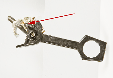
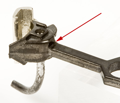
The edge(s) that will need to be modified so knuckle closes all the way. -
The iron wire trip pin you removed in Step 2 has two ears mashed out of its sides where it attaches to knuckle. These will need to be filed down until they are slightly fatter than the rest of the wire, but NOT down to the same size. These ears will be what holds the knuckle to the trip pin. Supporting the head of the coupler and using an unmodified coupler as a guide as the rotation of the trip pin relative to the knuckle, reinstall the knuckle and press trip pin back in place. You will be forcing the fat part of the trip pin into a hole that is too small for it, so some force will be required. Grip the trip pin just outside of the shank housing and press it in a little bit at a time. Never grab the free end of the trip pin and press from there. (You’ll bend the wire and send the coupler flying!)
Trip pin “ears” that will need filing.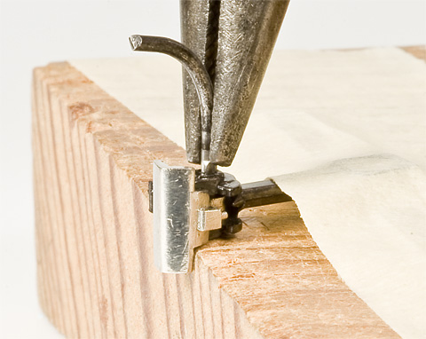
Pliers being used to insert trip pin wire a little bit at a time. - Replace coiled spring with a pair of tweezers.
For Slotted, Link & Pin Draw Head (Modified Shank. Only Use with Centerset Shank Couplers.):
- Follow Steps 1-5 as above.
-
File or shave using a razor blade, the fillet in the inside corner, between the back of the head and the top of the shank square.
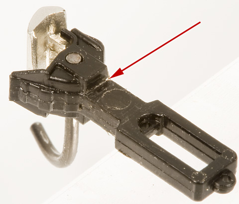
File this inside corner square. -
Drill a hole through the shank, centered on the shank, up against the back of the head, to accommodate the mounting pin for the slotted shank addition. Measure your mounting pin and the drill a hole one drill bit size smaller. It needs to be a press fit! Always double check your particular mounting pin, or, if in doubt, start a couple sizes smaller and work your way up.
For the FMW-4008 or FMW-4009 Extended Knuckles:
- Use a #77 drill bit.
For the FMW-4010 Extended Knuckles:
- Use a #74 drill bit.
Drill here. - Measure the pin used in your slotted, link & pin draw head. Drill one drill bit size larger, through the detent cast into the slotted shank extension casting. Be careful to keep the drill bit square to the part.
- Remove the slotted shank addition casting from the sprue and file the end to match the curve cast into it.
-
Press the mounting pin on the slotted shank addition casting into the hole drilled through the shank in Step 3. Using the same drill used in Step 4, drill through the center of the shank, through the hole drilled through the slotted shank addition casting.
Drill like this. -
Trim the coupler shank to match the length and shaper of the slotted shank addition casting. Note: the factory shank on #803 couplers will have to thinned, from the bottom, to fit you particular draw head!
Shank trimmed and rounded. - Replace coiled spring with a pair of tweezers.
Tall Extended Knuckle Replacement Castings for Kadee® #5 Head, McHenry™ HO Couplers, or Bachmann® E-Z Mate® Mark II HO Couplers:
Includes one pair of lost wax, “white bronze,” tall (approximately 0.270″ to 0.280″ tall) extended knuckle castings that can used to convert Kadee
| Stock No. | Description | Price |
|---|---|---|
| FMW-4008 | Pair of tall, extended knuckle replacement castings for Kadee | $6.50 |
Short Extended Knuckle Replacement Castings for Kadee® #5 Head, McHenry™ HO Couplers, or Bachmann® E-Z Mate® Mark II HO Couplers:
Includes one pair of lost wax, “white bronze,” short (approximately 0.200″ to 0.205″ tall) extended knuckle castings that can used to convert Kadee
| Stock No. | Description | Price |
|---|---|---|
| FMW-4009 | Pair of short, extended knuckle replacement castings for Kadee | $6.50 |
Extended Knuckle Replacement Castings for Kadee® #803 On3 Couplers:
Includes one pair of lost wax, “white bronze,” (approximately 0.300″ to 0.310″ tall) extended knuckle castings that can used to convert Kadee
| Stock No. | Description | Price |
|---|---|---|
| FMW-4010 | Pair of extended knuckle replacement castings for Kadee | $6.50 |
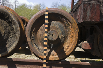
O/On3/On30/On2 Griffin Wheel Co., 26″ Single Plate, Chilled Iron Wheels (in Celcon® )
Wheel grinder track at West Side & Cherry Valley (Photo by Jerry Kitts, November 1978 at Tuolumne), filled with trucks using this Griffin 26″ single plate wheel. (No, we have no explanation for why the West Side thought it was OK to grind down the surface of chilled iron wheels.)
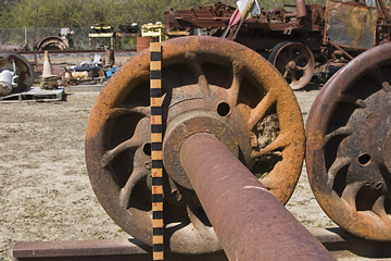
Pacific Car & Foundry, connected-truck, log car trucks from an ex-Swayne car. (Photo by Jerry Kitts, May 1978, at Yosemite Mountain Sugar Pine Railroad.) The first axle has this Griffin single plate wheel. The West Side had a habit of using any available wheel in any truck, as needed, so long as the diameter matched. We’ve even found a truck with four different wheels, including one A. Whitney & Sons wheel from the 19th century!
New, scale, Griffin Wheel Co., 26″ wheels! And we do mean scale (O Scale to be exact, gauge to be determined by axle length, just like the real thing). These are very accurate copies of their 1920’s, 26″ single plate, chilled iron wheels as ordered for and used on the West Side Lumber Co. These wheels are based on exacting measurements of those preserved in the Roaring Camp & Big Trees collection in Felton, California. We even cut the wheel tread to an exact match of period M.C.B./A.A.R. recommended practices (no mangling to match RP25 here). Also note as you look at the photos and read the captions, these wheels are only 0.5417″ in diameter (aka the detail really is that small)! Production has begun and the first batch has already shipped!
Griffin 26″ Wheels Sets (FMW-4011-On3) installed in MacLeod Western T-17-2 Truck w/FMW-4000 Wooden Brake Beams, FMW-4004 Truck Brake Levers, and FMW-4007 Celcon
Griffin 26″ Wheels Sets (FMW-4011-On3) installed in MacLeod Western T-14 Truck w/FMW-4000 Wooden Brake Beams, FMW-4004 Truck Brake Levers, and FMW-4007 Celcon
Works in D&RGW trucks too! While the vast majority of the D&RGW’s wheels were Griffin 26″ Washburn pattern wheels, they existed for so long and had so many cars, that you can find examples of just about every kind of wheel. Including paper, single plate, and even turned steel wheels. Though they obviously got their wheels from the Denver plant, not the Tacoma plant.
Griffin 26″ Wheels Sets (FMW-4011-On3) installed in a San Juan Car Co. D&RGW, 3′ 7″ Freight Car truck in brown. (Axle holes in San Juan trucks have to be drilled out as they are designed for a shorter, pointed axle.) |
Griffin 26″ Wheels Sets (FMW-4011-On3) installed in a Grandt Line Products 3056 D&RGW Narrow Gauge Passenger Car Truck with Cast Steel Bearing Bolster w/3057 Brake Set. (With brake beams lowered to correct height for 26″ wheels.) |
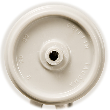
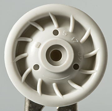
Front and Back of the new wheel. The wheels are shot from the center of the wheel, so there aren’t any nicks in the flange or along the rim. Nor did we use knock out pins. The letters were cut with a 0.003″ diameter end mill for scale 1/8″ thick letters! As the lettering cast into this wheel indicates, Griffin’s foundry in Tacoma, Washington cast this wheel specifically to order for the West Side Lumber Co. (WSL) on February 20, 1922 (the prototype for this specific wheel was serial # T263445). The “T1” refers to the taped measurement of the diameter of the wheel. I have no idea what the “G” and “3G” refer to.
A cross sectional view (cutting Celcon
Assembled Wheel Sets (On3). We follow Cliff Grandt’s axle design for On3 - an exposed axle 1/16″ in diameter with an overall length of 1.165″. We’re using thin-walled, stainless steel, hypodermic tubing to simulate the straight, 5″ diameter axles of the prototype. They are not effected by under-track uncoupling magnets.
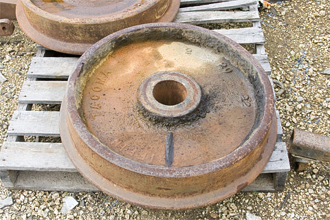
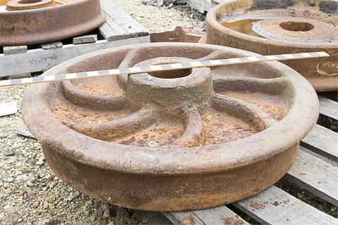
Griffin 26″, single plate wheel being measured and photographed at Roaring Camp & Big Trees, Felton, CA, on February 10, 2012 (10 days short of 90 years after the wheel was cast).
Produced in a bright, metal-like color, these wheels are cast in Celcon
Griffin Wheel Co., 26″ Single Plate, Chilled Iron Wheels (in Celcon® ):
These wheel sets include four axle sets in the following gauges. Recommended for use in Grandt Line Products, MacLeod Western, and most brass and white metal trucks. Not recommended for use in San Juan Car Co. trucks or any truck that uses pointed axles. All sales of custom axles are final and are non-returnable/non-refundable.
| Gauge | “Back-to-Back” Wheel Spacing | Axle Length | Description | Stock No. | Price |
|---|---|---|---|---|---|
| On2 | 0.416″ | 0.915″ | NMRA Standard On2 on NWSL Length Axles | FMW-4011-On2 | $10.00 |
| On30 | 0.566″ | 1.025″ | NMRA Standard On30 on HO Length Axles | FMW-4011-On30a | $10.00 |
| On30 | 0.566″ | 1.165″ | NMRA Standard On30 on On3 Length Axles (for use in On3 trucks) | FMW-4011-On30b | $10.00 |
| On3 | 0.666″ | 1.165″ | NMRA Standard On3 on Cliff Grandt/NWSL Length Axles | FMW-4011-On3 | $10.00 |
| Custom | Specified by Customer |
Specified by Customer |
Wheel sets built to customer’s specifications | FMW-4011-Custom | $10.00 |
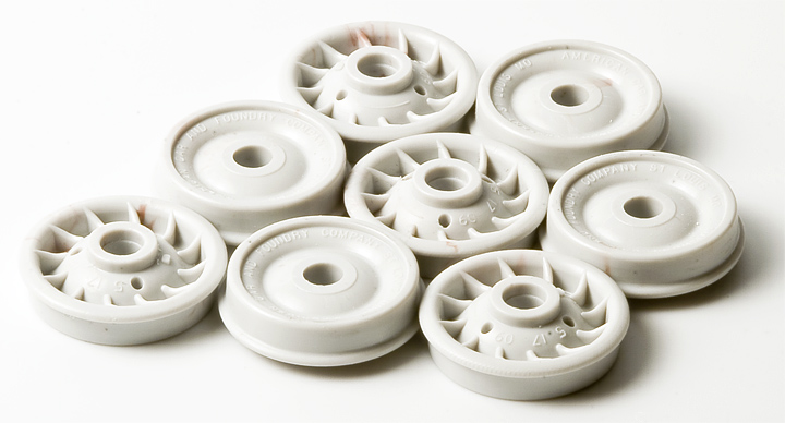
Griffin Wheel Co., 26″ Single Plate, Chilled Iron (in Celcon® ) Scenery Wheels
Does your junk or clutter pile need detailed, scale wheels? Does your wheel or car shop need a supply of new or used wheels? Does your snow plow or boom car need counter weights? Well, look no further! As we switch from styrene to Celcon
26″ Griffin Scenery Wheels:
Includes 8, Celcon
| Scale. | Stock No. | Description | Price |
|---|---|---|---|
| O | FMW-4011-Scene | Set of 8, Celcon | $3.00 |
Braided Fire Hose
|
Orange FMW-4012 installed on completed prototype model for kit FMW-2212. |
FMW-4012’s in some of the available colors. |
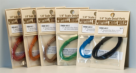
We originally supplied these with our 20′ Fire Car kit. This heavy, lead core trolling line is covered in colored, woven fabric and makes for a very convincing, scale, braided fire hose. Normally available in expensive, 50 yard and longer reels, we’re making it available here in convenient 6′ long lengths. While available in many different colors, it is easily painted to match any color you like. The lead core allowing you to mold the “hose” to any shape.
Note: The manufacturer has discontinued this product and only a limited supply is remaining! Don't miss out, order yours today!
| Warning!: |
| This product contains lead, a chemical known to the state of California to cause cancer, birth defects, or reproductive harm. Wash hands after use. Use Appropriately. Do not eat ;-) |
Braided Fire Hose:
Includes approximately 6′ of braided fire hose, in one of the following colors (Please check on the availability of the color want before ordering).
| red | orange | light brown | dark brown |
| green | teal | dark blue | dark gray |
| cyan | yellow | green-brown mix | blue-white mix |
| white | gray | yellow-green mix |
We are also offering Fire Hose in two different sizes or scale diameters:
| Large FMW-4012 | Small FMW-4013 |
|
|---|---|---|
| HO | ⌀ 3″ | ⌀ 2⅜″ |
| S | ⌀ 2¼″ | ⌀ 1¾″ |
| O | ⌀ 1¾″ | ⌀ 1¼″ |
| Scale | Stock No. | Description | Price |
|---|---|---|---|
| O | FMW-4012 | Large Braided Fire Hose. Specify color when ordering. | $3.00 |
| O | FMW-4013 | Small Braided Fire Hose. Specify color when ordering. | $3.00 |
All text, images, and drawings ©2012, 2014, 2016 Foothill Model Works.
Rev. 12/06/2017.